Networking, Security & Cloud Knowledge

Sunday, December 26, 2010

013 DMVPN

DMVPN between Router 1 with public static ip and Router 2 with DSL line with dynamic ip

Router 1 - fa0 - Public internet connection ( 20.20.20.2/30) - { internet cloud} - ADSL -(192.168.1.2/24) fa1 - Router 2

Router 1

conf t
crypto isakmp policy 25
encr 3des
hash md5
authentication pre-share
crypto isakmp key r1-r2dmvpn address 0.0.0.0 0.0.0.0
crypto ipsec transform-set ESP-AES-SHA esp-aes esp-sha-hmac
mode transport
crypto ipsec profile DMVPN
set security-association lifetime seconds 28800
set transform-set ESP-AES-SHA
interface Tunnel0
ip address 10.10.10.1 255.255.255.0
ip mtu 1400
ip nhrp authentication VPNkey
ip nhrp map multicast dynamic
ip nhrp network-id 123456
ip nhrp holdtime 360
ip virtual-reassembly
ip tcp adjust-mss 1360
load-interval 60
delay 1000
qos pre-classify
tunnel source FastEthernet0
tunnel mode gre multipoint
tunnel key 100001
tunnel protection ipsec profile DMVPN shared

end
Configuration on Router 2
conf t
crypto isakmp policy 1
encr aes 256
authentication pre-share
group 5
crypto isakmp key r1-r2dmvpn address 20.20.20.2
crypto ipsec security-association replay window-size 1024
crypto ipsec transform-set ESP-AES-SHA esp-aes esp-sha-hmac
mode transport
crypto ipsec profile DMVP
set security-association lifetime seconds 28800
set transform-set ESP-AES-SHA
interface Tunnel1
ip address 10.10.10.2 255.255.255.0
ip mtu 1400
ip nhrp authentication VPNkey
ip nhrp map 10.10.10.1 20.20.20.2
ip nhrp network-id 123456
ip nhrp holdtime 360
ip nhrp nhs 10.10.10.1
ip nhrp registration no-unique
ip tcp adjust-mss 1360
delay 1000
qos pre-classify
tunnel source FasteEthernet 1
tunnel mode gre multipoint
tunnel key 100001
tunnel protection ipsec profile DMVPN shared
end
Tuesday, November 30, 2010

[<< INDEX PAGE ][012][ Building Site - to - Site VPN configuration example]

sh crypto isakmp poliy
sh crypto isakmp key
sh crypto ipsec transformset
sh crypto map

sh crypto isakmp sa
sh crypto ipsec sa
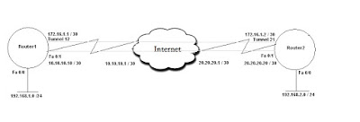
Network Diagram


Configuration on Router1

Step 1: Create Isakmp policy
crypto isakmp policy 10
encr 3des
hash md5
authentication pre-share

Step 2: Create Pre-Share Key
crypto isakmp key abcdefg address 20.20.20.20

Step 3: Create transform set
crypto ipsec transform-set test1 esp-3des esp-md5-hmac
mode transport

Step 4: Create Crypto Map
crypto map MAP1 10 ipsec-isakmp
description Tunnel to Router2
set peer 20.20.20.20
set transform-set test1
match address VPN-R1toR2

Step 5: Create ACL
ip access-list extended VPN-R1toR2
Remark Ecrypted traffic from Router1 to Router2
permit host 10.10.10.10 host 20.20.20.20

Step 6: Create Tunnel interface
interface tunnel 12
ip address 172.16.1.1 255.255.255.252
tunnel source fa 0/1
tunnel destination 20.20.20.20
tunnel mode gre
crypto map MAP1

Step 7: Configure WAN interface
interface fa 0/1
ip address 10.10.10.10 255.255.255.255
crypto map MAP1

Step 8: Static Route to PEER address
ip route 20.20.20.20 255.255.255.255 10.10.10.1


======================================================

Configuration on Router2

Step 1: Create Isakmp policy
crypto isakmp policy 10
encr 3des
hash md5
authentication pre-share

Step 2: Create Pre-Share Key
crypto isakmp key abcdefg address 10.10.10.10

Step 3: Create transform set
crypto ipsec transform-set test1 esp-3des esp-md5-hmac
mode transport

Step 4: Create Crypto Map
crypto map MAP2 10 ipsec-isakmp
description Tunnel to Router2
set peer 10.10.10.10
set transform-set test2
match address VPN-R2toR1

Step 5: Create ACL
ip access-list extended VPN-R2toR1
Remark Ecrypted traffic from Router2 to Router1
permit host 20.20.20.20 host 10.10.10.10

Step 6: Create Tunnel interface
interface tunnel 21
ip address 172.16.1.2 255.255.255.252
tunnel source fa 0/1
tunnel destination 10.10.10.10
tunnel mode gre
crypto map MAP2

Step 7: Configure WAN interface
interface fa 0/1
ip address 20.20.20.20 255.255.255.255
crypto map MAP2

Step 8: Static Route to PEER address
ip route 10.10.10.10 255.255.255.255 20.20.20.1

Wednesday, November 24, 2010

011 hp switches command


HP procurve 2510-48 switch


Hp_procurve# conf t

Hp_procurve(config)# hostname xyz <>


---------------------------------------------------------------------------------------------

Hp_procurve (conifg)# password manager <>

Hp_procurve (conifg)# password operator


----------------------------------------------------------------------------------------------

Hp_procurve(config)# management-vlan 1 <>

Hp_procurve(config)# vlan 1
Hp_procurve(vlan-1)# ip address 192.168.1.10 255.255.255.0


Hp_procurve(config)# management-vlan 10

Hp_procurve(config)# vlan 10

Hp_procurve(vlan-10)# ip address 192.168.10.10 255.255.255.0


Hp_procurve (config)# ip default-gateway 192.168.1.1


-----------------------------------------------------------------------------------------------------------------

Hp_procurve (conifg)# ip authorized-manager =>range of address who can mange switch


Hp_procurve (conifg)# loggin <>

Loggin facility local 0


-----------------------------------------------------------------------------------------------------------------


Configuring SNMP

Hp_procurve(config)# snmp-server community ASCII-STRING operator

Hp_procurve (config) # snmp-server host

-----------------------------------------------------------------------------------------------------------------

Configuring VLAN

Hp_procurve(config) # vlan 32

Hp_procurve(vlan-32)# name vlan_name

Hp_procurve (config)# vlan 32 untagged ethernet 1-46 =>port Ethernet 1-46 is in vlan 32


Hp_procurve(config) # vlan 4

Hp_procurve(vlan-32)# name vlan_name

Hp_procurve (config)# vlan 32 untagged ethernet 47-48 =>port Ethernet 47-148 in vlan 4


Hp_procurve(config) # vlan 32

Hp_procurve(vlan-32)# name vlan_name

Hp_procurve (config)# vlan 32 untagged ethernet 1-46 =>port Ethernet 1-46 is in vlan 32


Configuring Trunk

Hp_procurve(config)# trunk Ethernet 24 trk 1


Hp_procurve (conifg)# vlan 32 tagged Ethernet 51

Hp_procurve (conifg)# vlan 4 tagged Ethernet 51

Hp_procurve (conifg)# vlan 10 tagged Ethernet 51


----------------------------------------------------------------------------------------------------------------

Configuring AAA authentication using TACACS

Hp_procurve(config)# aaa authentication num-attempts {1-10}

Hp_procurve (conifg)# aaa authentication login privilege-mode

Hp_procurve (conifg)# aaa authentication telnet login tacacs local

Hp_procurve (conifg)# aaa authentication telnet enable tacacs local

Hp_procurve (conifg)# tacacs-server host key


Sunday, November 14, 2010

010 - BGP

  1. BGP is path vector protocol
  2. BGP message types:
    Open - Used to form peer relationships
    Keepalive - Periodic maintenance of relationships
    Update - Communicates routing information Notification - Communicates an error
  3. BGP neighbor states:
    Idle
    Connect - A TCP connection is being attempted
    Active - A TCP connection has failed; the router is waiting to be contacted by its peer
    OpenSent - TCP session established, open message sent
    OpenConfirm - Waiting for a keepalive from the peer Established
  4. Path Attributes
    Attribute classes:
    Well-known mandatory attributes must be supported and included
    Well-known discretionary attributes must be supported but may not be included
    Optional transitive attributes don't have to be supported, but must be passed onto peer Optional nontransitive attributes don't have to be supported, and can be ignored
  5. BGP Attributes are as follows:
    [1] Weight (16-bit value) - Highest weight is preferred
    [2] Local Preference - Highest preferred
    [3] Router originated from local router - next hop 0.0.0.0
    [4] Shortest AS path
    [5] Lowest origin code ( IGP EGP ?)
    [6] Lowest MED ( Multi Exit Discriminator)
    [7] Choose EBGP route over IBGP route
    [8] Choose router through the nearest IGP neighbor as determined by the lowest IGP metric
    [9] Choose the Oldest route
    [10] Choose a path through the neighbor with the lowest router ID
    [11] Choose a path through the neighbor with the lowest IP address

[<< INDEX PAGE ][009][ Reverse Telnet]

Reverse Telnet gives the ability to telnet to a device, and then console to another device from there. For example, you could telnet to a router, and then console into a switch, or anything that has a console port.
Note: connect CONSOLE port of the Switch to AUX port of the router using ROLL OVER cable.
1 configure the AUX port
router#conf t
router(config)#line aux 0
router(config-line)#modem InOut
router(config-line)#transport input all
router(config-line)#transport output telnet
router(config-line)#speed 19200
router(config-line)#no exec
router(config-line)#stop bit 1
(config-line)#exit
router(config)# interface lo 0
router(config-line)#ip address [address] [mask]
router# show line
Tty Typ Tx/Rx A Modem Roty AccO AccI Uses Noise Overruns Int
0 CTY - - - - - 0 0 0/0 -
225 AUX 19200/19200 - inout - - - 0 0 0/0 -
* 226 VTY - - - - - 10 0 0/0 -
227 VTY - - - - - 0 0 0/0 -
228 VTY - - - - - 0 0 0/0 -
229 VTY - - - - - 0 0 0/0 -
230 VTY - - - - - 0 0 0/0 -


Now to telnet switch: telnet [lo address of router] 2225
{ where 2225 = 2000 + aux tty line number}

Saturday, November 13, 2010

009 - Arcive Command

ARCHIVE
archive
log config
logging enable
logging size 200
hidekeys
path tftp://tftp_server/
write-memory
time-period 43200
**********************************************************************
SNMP and Logging configuration
ip sla responder
logging source-interface Loopback0
logging [Logg_server_ip]

access-list 1 permit [NMS_server]

snmp-server community Public RO 1
snmp-server ifindex persist
snmp-server trap-source Loopback0
snmp-server source-interface informs Loopback0
snmp-server packetsize 1300
snmp-server queue-length 20
snmp-server location Companyname . THIS_LOCATION
snmp-server contact Site-Contact [contact number]
snmp-server system-shutdown
snmp-server enable traps eigrp
snmp-server enable traps envmon
snmp-server enable traps bgp
snmp-server enable traps memory bufferpeak
snmp-server enable traps cnpd
snmp-server enable traps config
snmp-server enable traps entity
snmp-server enable traps fru-ctrl
snmp-server enable traps event-manager
snmp-server enable traps cpu threshold

************************************************************************
Netflow configuration
interface fa 0
ip route-cache flow

ip flow-export source Loopback0

ip flow-export version 5
ip flow-export destination 10.10.10.10 2020
snmp-server ifindex persist
ip flow-cache timeout active 3

008 SSH & AAA configuration

AAA configuration
username [username] privilege 15 secret [Password]

aaa new-model
!
aaa authentication login default group tacacs+ local
aaa authentication enable default group tacacs+ enable

aaa authorization config-commands

aaa authorization exec default group tacacs+ local

aaa authorization commands 1 default group tacacs+ local
aaa authorization commands 2 default group tacacs+ local
aaa authorization commands 3 default group tacacs+ local
aaa authorization commands 4 default group tacacs+ local
aaa authorization commands 5 default group tacacs+ local
aaa authorization commands 15 default group tacacs+ local

aaa accounting connection default start-stop group tacacs+
aaa accounting exec default start-stop group tacacs+

aaa accounting commands 0 default start-stop group tacacs+
aaa accounting commands 1 default start-stop group tacacs+
aaa accounting commands 2 default start-stop group tacacs+
aaa accounting commands 3 default start-stop group tacacs+
aaa accounting commands 4 default start-stop group tacacs+
aaa accounting commands 5 default start-stop group tacacs+
aaa accounting commands 15 default start-stop group tacacs+
!
!
aaa session-id unique
!


ip tacacs source-interface Loopback0

tacacs-server host {TACAC-SERVER-ADDRESS} timeout 8
tacacs-server directed-request
tacacs-server key [ACS_Key]
******************************************************************
SSH configuration
config t
crypto key generate rsa gerenal-keys modulus 1024 {1024 OR 2048}
ip ssh source-interface loopback 0
ip ssh version 2


line vty 0 15
transport input ssh
transport output telnet ssh

007.1 - GATEWAY REDUNDANCY-HSRP

Hot Standby Router Protocol (HSRP)

  • HSRP is Cisco proprietary, but defined in RFC 2281.
  • HSRP routers multicast to the all-routers address 224.0.0.2 on UDP port 1985.
  • HSRP group numbers (0 – 255) are only significant to an interface.
  • HSRP virtual MAC in the range 0000.0c07.acXX where the last 8 bits represent the standby group.
  • HSRP priority ranges from 0 to 255; default is 100.
  • The default hello timer is 3 seconds; holddown timer is 10 seconds.
  • preempt is not enabled by default
  • HSRP interface states: Disabled Init Listen Speak Standby Active
  • Cisco devices by default use the plaintext string "cisco" for authentication.
  • Plaintext or MD5 authentication can be used
  • Active router election :The highest priority wins; highest IP wins a tie.
  • The router’s priority will be decremented by the associated value (default 10) if the tracked interface fails.


HSRP group configuration:
standby 1 ip [virtual_ip]

Timers can be adjusted:
standby 1 timers [hello] [dead]

By default a router with higher priority cannot preempt the current active router; this can be allowed:
standby 1 priority [priority]
standby 1 preempt

Minimum defines the time the router must wait after it becomes HSRP-capable for the interface. Reload defines the time it must wait after reloading.


Conceding the Election
A router can be configured to withdraw from active status if one or more of its other interfaces fail:
standby 1 track [interface][value]

The router’s priority will be decremented by the associated value (default 10) if the tracked interface fails.
If another router now has a higher priority and has been configured to preempt, it will take over as the active router for the group.
Enabling Authentication
standby 1 authentication md5 key-string [password]
Verification
show standby [brief] [interface]
**************************************************************************


007.2 - GATEWAY REDUNDANCY-GLBP

Gateway Load Balancing Protocol (GLBP)

  • GLBP is Cisco proprietary, and acts like HSRP/VRRP with true load-balancing capability: all routers in a group forward traffic simultaneously.
  • GLBP group numbers range from 0 to 1023. Priorities range from 0 to 255 (default is 100).
  • GLBP advertisements are multicast to 224.0.0.102
  • hello/hold timers (default 3/10 seconds)
  • Timers only need to be configured on the AVG; other routers will learn from it.
  • Active Virtual Gateway (AVG)
    The AVG has the highest priority in the GLBP group (or the highest IP address in the event of a tie); it answers all ARP requests for the group’svirtual IP address.
  • Active Virtual Forwarder (AVF)
    All routers sharing load in GLBP are AVFs.
    If an AVF fails, the AVG reassigns its virtual MAC to another router.
  • Two timers are used to age out the virtual MAC of a failed AVF:
    Redirect timer (default 600 seconds) – Determines when the AVG will stop responding to ARP requests with the MAC of the failed AVF
    Timeout timer (default 4 hours) – Determines when the failed AVF is no longer expected to return, and its virtual MAC will be flushed from the GLBP group
  • AVFs are assigned a maximum weight (1-254; default is 100).


IP address(es), router preemption, and hello/hold timers (default 3/10 seconds) can be configured like for HSRP:
glbp 1 ip [virtual_ip]
glbp 1 priority [priority]
glbp 1 preempt
glbp 1 forwarder preempt
Configuring the timers:
glbp 1 timer [hello] [dead]
glbp 1 timer redirect [redirect] [time-out]
Interfaces can be tracked and the AVF’s weight adjusted when interfaces go down
glbp 1 weighting [weight] lower [lower] upper [upper]
glbp 1 weighting track [object] decrement [value]
When the upper or lower threshold is reached, the AVF enters or leaves the group, respectively.
Load Balancing
Up to four virtual MACs can be assigned by the AVG.
Traffic can be distributed among AVFs using one of the following methods:
Round robin (default) – Each new ARP request is answered with the next MAC address available; traffic is distributed evenly among AVFs
Weighted – AVFs are assigned load in proportion to their weight
Host-dependent – Statically maps a requesting client to a single AVF MAC
Configuring load balancing:
glbp 1 load-balacing [method]
Verification
show glbp [brief]


[<< INDEX PAGE ][007.3][ GATEWAY REDUNDANCY- VRRP]

Virtual Router Redundancy Protocol (VRRP)

  • Standards-based alternative to HSRP, defined in RFC 2338.
  • VRRP refers to the active router as the master router; all others are in the backup state.
  • VRRP virtual MAC from the range 0000.5e00.01XX where the last eight bits represent the group number.
  • VRRP advertisements are multicast to 224.0.0.18, using IP protocol 112.
  • VRRP advertisements are sent in 1-second intervals by default; backup routers can optionally learn the interval from the master router.
  • VRRP routers will preempt the master by default if they have a higher priority.
  • VRRP is unable to track interfaces and concede an election.
VRRP Configuration
VRRP configuration is very similar to HSRP configuration:
vrrp 1 ip [virtual_ip]
vrrp 1 timers {advertise [hello]learn}
vrrp 1 priority [priority]
vrrp 1 preempt
vrrp 1 authentication md5 key-string [password]
vrrp 1 track [object]
decrement
Verification
show vrrp [brief]


Sunday, March 7, 2010

006 - IOS installation on Cisco Router

Requirenment: Router connected to ethernet network
Tftp server ( solarwinds ) with ios image on root directory

For 1700 series Router
rommon> set
IP_ADDRESS=192.168.1.2
IP_SUBNET_MASK=255.255.0.0
TFTP_SERVER=192.168.1.10
DEFAULT_GATEWAY=192.168.1.1
TFTP_FILE={the name of the IOS that is saved on the PC}

rommon > tftpdnld


rommon>reset


For 2500 series Router

Steps:
Step 2:Change the configuration register to boot the ROM(BOOT) image. Configuration register to be used is 0×2141
Step 3: Initialize the router by issuing the i command
Step 4 Assign an IP address to the Ethernet interface and configure a default gateway (if required).


Commands:
>o/r 0×2141>i


Press RETURN to get started!

Router(boot)>enable
Router(boot)#config t
Router(boot)(config)#interface e0
Router(boot)(config-if)#ip add 10.1.1.20 255.255.255.0
Router(boot)(config-if)#no shut
Router(boot)(config-if)#exit
NOTE: The line below is optional if your TFTP server is not on the same network
Router(boot)(config)#ip default-gateway 10.1.1.254
Router(boot)(config)#end

Router(boot)#copy tftp flash